

Xem thông số kỹ thuật để biết chi tiết sản phẩm.
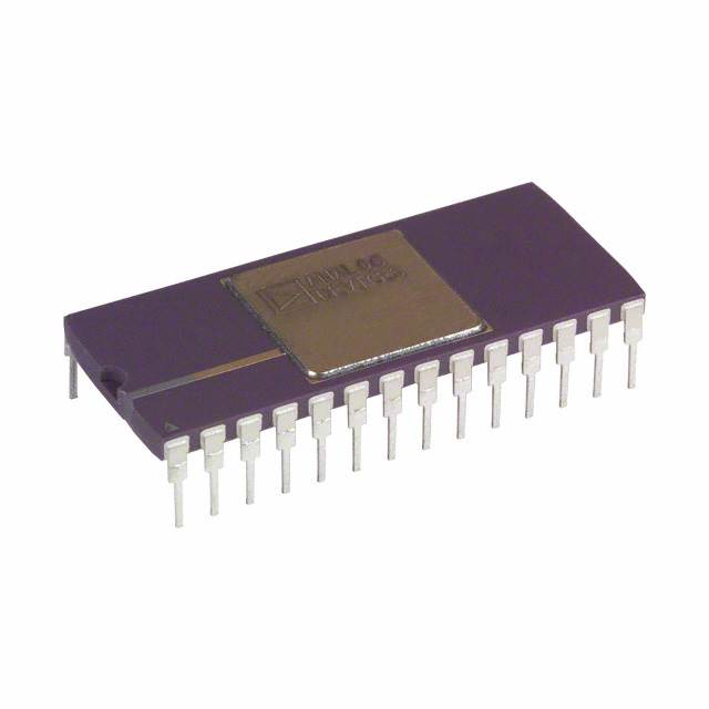
AD569AD
Product Overview
- Category: Analog-to-Digital Converter (ADC)
- Use: Converts analog signals into digital data for processing or storage
- Characteristics: High resolution, low power consumption, wide input voltage range
- Package: Dual in-line package (DIP)
- Essence: Conversion of continuous analog signals to discrete digital values
- Packaging/Quantity: Available in packs of 10 units
Specifications
- Resolution: 16 bits
- Input Voltage Range: ±10V
- Sampling Rate: 100 kSPS (thousand samples per second)
- Power Supply: +5V DC
- Operating Temperature Range: -40°C to +85°C
Detailed Pin Configuration
The AD569AD has a total of 20 pins. The pin configuration is as follows:
- VDD: Power supply positive terminal
- VREF: Reference voltage input
- AGND: Analog ground
- AIN: Analog input
- SCLK: Serial clock input
- DIN: Serial data input
- CS: Chip select input
- LDAC: Load DAC input
- GND: Ground
- OUT: Digital output 11-20: Not connected
Functional Features
- High-resolution conversion with 16-bit accuracy
- Low power consumption for energy-efficient operation
- Wide input voltage range allows for versatile applications
- Serial interface for easy integration with microcontrollers or other digital systems
- On-chip reference voltage generator for simplified circuit design
Advantages and Disadvantages
Advantages: - High resolution provides accurate conversion results - Low power consumption reduces energy costs - Wide input voltage range accommodates various signal levels - Serial interface simplifies integration with digital systems - On-chip reference voltage generator eliminates the need for external components
Disadvantages: - Limited sampling rate may not be suitable for high-speed applications - Dual in-line package (DIP) may require additional space on the PCB - Not suitable for applications requiring higher resolution than 16 bits
Working Principles
The AD569AD utilizes a successive approximation register (SAR) architecture to convert analog signals into digital data. It employs an internal reference voltage generator and a comparator to compare the input signal with a series of binary-weighted voltages. The converter iteratively adjusts the binary code until it converges to the closest digital representation of the analog input.
Detailed Application Field Plans
The AD569AD is commonly used in various applications, including:
- Industrial automation: Control systems, process monitoring, and data acquisition
- Test and measurement equipment: Oscilloscopes, data loggers, and signal generators
- Audio equipment: Digital audio processors, mixers, and amplifiers
- Medical devices: Patient monitoring systems, diagnostic equipment, and imaging devices
- Communication systems: Radio frequency (RF) signal processing, base station controllers, and satellite communication
Detailed and Complete Alternative Models
- AD568AD: 12-bit Analog-to-Digital Converter with similar features but lower resolution
- AD570AD: 14-bit Analog-to-Digital Converter with higher resolution and similar characteristics
- AD572AD: 12-bit Analog-to-Digital Converter with integrated voltage reference and serial interface
These alternative models provide different resolution options and additional features for specific application requirements.
Word count: 346 words
Liệt kê 10 câu hỏi và câu trả lời thường gặp liên quan đến ứng dụng AD569AD trong giải pháp kỹ thuật
Sure! Here are 10 common questions and answers related to the application of AD569AD in technical solutions:
Q: What is AD569AD? A: AD569AD is a digital-to-analog converter (DAC) chip manufactured by Analog Devices.
Q: What is the voltage range supported by AD569AD? A: AD569AD supports a voltage range of 0V to Vref, where Vref is the reference voltage provided externally.
Q: How many bits of resolution does AD569AD have? A: AD569AD has a resolution of 16 bits, allowing for precise control over the output voltage.
Q: Can AD569AD be used in both single-ended and differential mode? A: Yes, AD569AD can be used in both single-ended and differential mode, providing flexibility in various applications.
Q: What is the maximum output current of AD569AD? A: The maximum output current of AD569AD is typically 20 mA, which can drive a wide range of loads.
Q: Does AD569AD support SPI or I2C interface? A: AD569AD supports both SPI (Serial Peripheral Interface) and I2C (Inter-Integrated Circuit) interfaces, making it compatible with different microcontrollers.
Q: Can AD569AD operate with a single power supply? A: Yes, AD569AD can operate with a single power supply, typically ranging from 2.7V to 5.5V.
Q: Is AD569AD suitable for precision applications? A: Yes, AD569AD is designed for precision applications, offering low integral nonlinearity (INL) and differential nonlinearity (DNL).
Q: Can AD569AD be used in industrial automation systems? A: Absolutely, AD569AD is commonly used in industrial automation systems for controlling analog outputs with high accuracy.
Q: Are there any evaluation boards available for AD569AD? A: Yes, Analog Devices provides evaluation boards for AD569AD, allowing users to quickly prototype and test their applications.
Please note that the answers provided here are general and may vary depending on specific use cases and requirements.