Xem thông số kỹ thuật để biết chi tiết sản phẩm.

Encyclopedia Entry: 74HCT00S14-13
Product Overview
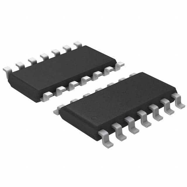
The 74HCT00S14-13 is a digital integrated circuit belonging to the category of logic gates. It is widely used in various electronic devices and systems for logical operations. This component exhibits specific characteristics that make it suitable for applications requiring high-speed and low-power consumption. The 74HCT00S14-13 is packaged in a small outline package (SOP) with 14 pins, ensuring ease of integration into electronic circuits.
Specifications
- Category: Logic Gates
- Use: Logical operations in electronic devices and systems
- Characteristics: High-speed, low-power consumption
- Package: Small Outline Package (SOP)
- Pin Configuration: Detailed pin configuration provided below
- Packaging/Quantity: Varies based on supplier, typically available in reels or tubes
Pin Configuration
The 74HCT00S14-13 features 14 pins arranged as follows:
Pin 1: Input A1
Pin 2: Input B1
Pin 3: Output Y1
Pin 4: Ground (GND)
Pin 5: Input A2
Pin 6: Input B2
Pin 7: Output Y2
Pin 8: VCC (Power Supply)
Pin 9: Input A3
Pin 10: Input B3
Pin 11: Output Y3
Pin 12: Input A4
Pin 13: Input B4
Pin 14: Output Y4
Functional Features
The 74HCT00S14-13 is known for its excellent functional features. It operates as a quad 2-input NAND gate, providing four independent NAND gates in a single package. Each gate accepts two inputs and produces an inverted output. This component offers high-speed operation, making it suitable for time-critical applications. Additionally, it consumes low power, contributing to energy-efficient designs.
Advantages and Disadvantages
Advantages: - High-speed operation enables efficient processing of logical operations. - Low-power consumption contributes to energy-efficient designs. - Compact SOP package facilitates easy integration into electronic circuits.
Disadvantages: - Limited number of gates per package may require multiple components for complex logic operations. - Sensitivity to voltage fluctuations may affect performance in unstable power supply conditions.
Working Principles
The 74HCT00S14-13 operates based on the principles of NAND gate logic. It takes two input signals and produces an inverted output signal. The internal circuitry of this component utilizes transistors and resistors to implement the logical function. By combining multiple gates, complex logical operations can be achieved.
Application Field Plans
The 74HCT00S14-13 finds extensive application in various electronic systems and devices that require logical operations. Some common application fields include: - Microprocessor-based systems - Digital communication systems - Industrial control systems - Consumer electronics - Automotive electronics
Alternative Models
For users seeking alternative options, several similar models are available in the market. These alternatives offer comparable functionality and can be considered as substitutes for the 74HCT00S14-13. Some popular alternative models include: - 74LS00 - SN74HC00 - CD4011B - MC14011B
In conclusion, the 74HCT00S14-13 is a logic gate integrated circuit widely used in electronic devices and systems. Its high-speed operation, low-power consumption, and compact package make it suitable for various applications. However, its limited number of gates per package and sensitivity to voltage fluctuations should be considered. With its working principles based on NAND gate logic, it finds application in diverse fields. Users can also explore alternative models with similar functionality.
Liệt kê 10 câu hỏi và câu trả lời thường gặp liên quan đến ứng dụng 74HCT00S14-13 trong giải pháp kỹ thuật
Sure! Here are 10 common questions and answers related to the application of 74HCT00S14-13 in technical solutions:
Q: What is the 74HCT00S14-13? A: The 74HCT00S14-13 is a specific model of integrated circuit (IC) that belongs to the 74HCT series. It is a quad 2-input NAND gate with Schmitt-trigger inputs.
Q: What is the purpose of the 74HCT00S14-13? A: The main purpose of the 74HCT00S14-13 is to perform logical operations, specifically NAND gates, in electronic circuits. It can be used for signal processing, data manipulation, and control applications.
Q: What voltage levels does the 74HCT00S14-13 support? A: The 74HCT00S14-13 supports a wide range of voltage levels, typically from 2V to 6V. It is compatible with both TTL and CMOS logic families.
Q: How many inputs does the 74HCT00S14-13 have? A: The 74HCT00S14-13 has four independent 2-input NAND gates, which means it has a total of eight input pins.
Q: Can the 74HCT00S14-13 be used for level shifting? A: Yes, the 74HCT00S14-13 can be used for level shifting between different voltage domains. Its Schmitt-trigger inputs help provide robust and reliable signal transitions.
Q: What is the maximum frequency at which the 74HCT00S14-13 can operate? A: The 74HCT00S14-13 can typically operate at frequencies up to 125 MHz, making it suitable for high-speed digital applications.
Q: Can the 74HCT00S14-13 be used in both digital and analog circuits? A: No, the 74HCT00S14-13 is primarily designed for digital logic applications. It is not recommended for use in analog circuits due to its inherent digital nature.
Q: What are the power supply requirements for the 74HCT00S14-13? A: The 74HCT00S14-13 requires a single power supply voltage (VCC) typically ranging from 2V to 6V. It also has a ground (GND) pin for reference.
Q: Can the 74HCT00S14-13 drive capacitive loads directly? A: Yes, the 74HCT00S14-13 has a relatively high output current capability, allowing it to drive small capacitive loads directly without additional buffering.
Q: Are there any specific precautions to consider when using the 74HCT00S14-13? A: It is important to avoid exceeding the maximum ratings specified in the datasheet, such as voltage levels and operating temperature. Additionally, proper decoupling capacitors should be used to minimize noise and ensure stable operation.

