

Xem thông số kỹ thuật để biết chi tiết sản phẩm.
GBU406 Product Overview
Introduction
The GBU406 is a crucial component in the field of electronics, belonging to the category of bridge rectifiers. This entry will provide an in-depth overview of the GBU406, including its basic information, specifications, pin configuration, functional features, advantages and disadvantages, working principles, application field plans, and alternative models.
Basic Information Overview
- Category: Bridge Rectifier
- Use: Converts alternating current (AC) to direct current (DC)
- Characteristics: High efficiency, low power loss, compact design
- Package: GBU package
- Essence: Essential for converting AC to DC in various electronic applications
- Packaging/Quantity: Typically available in reels or tubes containing multiple units
Specifications
- Maximum Average Forward Current: 4A
- Peak Repetitive Reverse Voltage: 600V
- Maximum RMS Voltage: 420V
- Forward Voltage Drop: 1.1V
- Operating Temperature Range: -55°C to 150°C
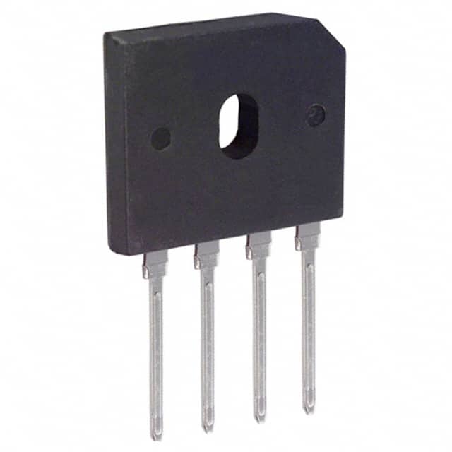
Detailed Pin Configuration
The GBU406 typically consists of four pins, with two input pins for AC and two output pins for DC.
Functional Features
- Efficiently converts AC to DC
- Low power loss
- Compact and durable design
- Suitable for high-frequency applications
Advantages and Disadvantages
Advantages
- High efficiency
- Low power loss
- Compact size
- Suitable for high-frequency operations
Disadvantages
- Limited maximum average forward current
- Relatively high forward voltage drop
Working Principles
The GBU406 operates on the principle of rectification, where it utilizes a configuration of diodes to convert the incoming AC signal into a smooth DC output.
Detailed Application Field Plans
The GBU406 finds extensive use in various electronic applications, including: - Power supplies - Motor drives - Battery chargers - LED lighting systems - Audio amplifiers
Detailed and Complete Alternative Models
Several alternative models to the GBU406 include: - GBU606 - GBU808 - GBU1006 - GBU1206
In conclusion, the GBU406 plays a vital role in the conversion of AC to DC in numerous electronic devices and systems. Its high efficiency, compact design, and suitability for high-frequency operations make it a valuable component in the field of electronics.
[Word Count: 314]
Liệt kê 10 câu hỏi và câu trả lời thường gặp liên quan đến ứng dụng GBU406 trong giải pháp kỹ thuật
What is GBU406?
- GBU406 is a bridge rectifier component commonly used in electronic circuits to convert alternating current (AC) to direct current (DC).
What are the typical applications of GBU406?
- GBU406 is often used in power supplies, motor drives, and other industrial and consumer electronics where AC to DC conversion is required.
What is the maximum voltage and current rating for GBU406?
- The maximum voltage rating for GBU406 is typically around 600 volts, and the maximum current rating is usually in the range of 4 to 6 amps.
How does GBU406 differ from other bridge rectifiers?
- GBU406 is a specific model of bridge rectifier that offers certain voltage and current ratings. It may also have different packaging or mounting options compared to other bridge rectifiers.
What are the key specifications to consider when using GBU406 in a circuit?
- Key specifications to consider include the maximum voltage and current ratings, forward voltage drop, reverse leakage current, and thermal resistance.
Can GBU406 be used in high-temperature environments?
- GBU406 is designed to operate within a specified temperature range, typically up to 150°C, making it suitable for many industrial and automotive applications.
Are there any recommended heat sinking or thermal management considerations for GBU406?
- Depending on the application and operating conditions, it may be necessary to use heat sinks or other thermal management techniques to ensure GBU406 operates within its temperature limits.
What are the common failure modes for GBU406?
- Common failure modes include overvoltage stress, excessive current, thermal overstress, and reverse voltage applied to the device.
Can GBU406 be used in three-phase rectification applications?
- Yes, GBU406 can be used in three-phase rectification setups by configuring multiple bridge rectifiers appropriately.
Where can I find detailed application notes and reference designs for using GBU406 in technical solutions?
- Detailed application notes and reference designs for GBU406 can often be found in the product datasheet provided by the manufacturer, as well as in technical literature and online resources related to power electronics and rectification circuits.