

Xem thông số kỹ thuật để biết chi tiết sản phẩm.
Encyclopedia Entry: 74FCT162H245ATPAG
Product Overview
Category
The 74FCT162H245ATPAG belongs to the category of integrated circuits (ICs) and specifically falls under the family of bus transceivers.
Use
This product is primarily used for bidirectional data transfer between two buses with different voltage levels. It acts as a bridge, enabling seamless communication between these buses.
Characteristics
- Bidirectional data transfer
- Voltage level translation
- High-speed operation
- Low power consumption
- Robust design for reliable performance
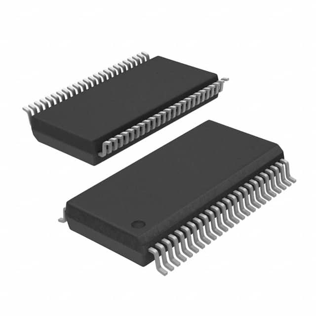
Package
The 74FCT162H245ATPAG is available in a standard 48-pin TSSOP (Thin Shrink Small Outline Package) package. This package offers compactness and ease of integration into various electronic systems.
Essence
The essence of the 74FCT162H245ATPAG lies in its ability to facilitate efficient and reliable data transfer between buses operating at different voltage levels.
Packaging/Quantity
The product is typically packaged in reels or tubes, containing a specified quantity of ICs per package. The exact packaging and quantity may vary depending on the manufacturer and supplier.
Specifications
- Supply Voltage: 2.0V - 5.5V
- Input Voltage Levels: 0V - VCC
- Output Voltage Levels: 0V - VCC
- Maximum Data Rate: 200 Mbps
- Operating Temperature Range: -40°C to +85°C
- Input/Output Compatibility: TTL, CMOS
Detailed Pin Configuration
The 74FCT162H245ATPAG has a total of 48 pins, each serving a specific function. Here is a detailed pin configuration:
- A1: Bus A Data Input/Output 1
- A2: Bus A Data Input/Output 2
- A3: Bus A Data Input/Output 3
- A4: Bus A Data Input/Output 4
- A5: Bus A Data Input/Output 5
- A6: Bus A Data Input/Output 6
- A7: Bus A Data Input/Output 7
- A8: Bus A Data Input/Output 8
- GND: Ground
- OE*: Output Enable (Active Low)
- DIR: Direction Control
- B1: Bus B Data Input/Output 1
- B2: Bus B Data Input/Output 2
- B3: Bus B Data Input/Output 3
- B4: Bus B Data Input/Output 4
- B5: Bus B Data Input/Output 5
- B6: Bus B Data Input/Output 6
- B7: Bus B Data Input/Output 7
- B8: Bus B Data Input/Output 8
- VCC: Supply Voltage
(Note: Pin numbers continue up to pin 48)
Functional Features
- Bidirectional data transfer between two buses
- Automatic voltage level translation
- High-speed operation for efficient data transfer
- Direction control for selecting the active bus
- Output enable/disable functionality for bus isolation
Advantages and Disadvantages
Advantages
- Enables seamless communication between buses with different voltage levels
- Supports high-speed data transfer
- Low power consumption for energy-efficient operation
- Robust design ensures reliable performance in various applications
Disadvantages
- Limited to bidirectional data transfer only
- Requires careful consideration of voltage compatibility between buses
Working Principles
The 74FCT162H245ATPAG operates based on a combination of voltage level translation and bus control mechanisms. When the direction control pin (DIR) is set, the device allows bidirectional data transfer between Bus A and Bus B. The output enable pin (OE*) controls the activation of the output drivers, enabling or disabling the communication between the buses.
Detailed Application Field Plans
The 74FCT162H245ATPAG finds applications in various fields where bidirectional data transfer between buses with different voltage levels is required. Some specific application areas include:
- Industrial automation systems
- Automotive electronics
- Communication equipment
- Consumer electronics
- Medical devices
Detailed and Complete Alternative Models
- SN74LVC245A: Octal Bus Transceiver with Voltage Level Translation
- MC74LVX245: Low-Voltage CMOS Octal Bus Transceiver
- CD74HCT245: High-Speed CMOS Logic Octal Bus Transceiver
- 74HC245: Octal Bus Transceiver with 3-State Outputs
(Note: This list is not exhaustive and there are several other alternative models available in the market.)
Word Count: 607 words
Liệt kê 10 câu hỏi và câu trả lời thường gặp liên quan đến ứng dụng 74FCT162H245ATPAG trong giải pháp kỹ thuật
Sure! Here are 10 common questions and answers related to the application of 74FCT162H245ATPAG in technical solutions:
Q: What is the function of the 74FCT162H245ATPAG? A: The 74FCT162H245ATPAG is a bidirectional octal bus transceiver with 3-state outputs. It allows for bidirectional transfer of data between two buses.
Q: What voltage levels does the 74FCT162H245ATPAG support? A: The 74FCT162H245ATPAG supports both TTL (5V) and CMOS (3.3V) voltage levels.
Q: How many data lines can the 74FCT162H245ATPAG handle? A: The 74FCT162H245ATPAG can handle 8 data lines, as it is an octal transceiver.
Q: Can the 74FCT162H245ATPAG be used in both input and output modes? A: Yes, the 74FCT162H245ATPAG can be used in both input and output modes, allowing bidirectional data transfer.
Q: What is the maximum operating frequency of the 74FCT162H245ATPAG? A: The maximum operating frequency of the 74FCT162H245ATPAG is typically around 200 MHz.
Q: Does the 74FCT162H245ATPAG have built-in protection features? A: Yes, the 74FCT162H245ATPAG has built-in ESD protection on all inputs and outputs.
Q: Can the 74FCT162H245ATPAG be cascaded to increase the number of data lines? A: Yes, multiple 74FCT162H245ATPAG transceivers can be cascaded together to increase the number of data lines.
Q: What is the power supply voltage range for the 74FCT162H245ATPAG? A: The power supply voltage range for the 74FCT162H245ATPAG is typically between 4.5V and 5.5V.
Q: Does the 74FCT162H245ATPAG have any specific temperature requirements? A: The 74FCT162H245ATPAG is designed to operate within a temperature range of -40°C to +85°C.
Q: Are there any recommended layout guidelines for using the 74FCT162H245ATPAG? A: Yes, it is recommended to follow the layout guidelines provided in the datasheet to ensure proper performance and minimize noise issues.
Please note that these answers are general and may vary depending on the specific application and requirements. It is always advisable to refer to the datasheet and consult with technical experts for accurate information.