

Xem thông số kỹ thuật để biết chi tiết sản phẩm.
IXGT30N120BD1
Product Overview
- Category: Power semiconductor device
- Use: High-power switching applications
- Characteristics: High voltage, high current capability, fast switching speed
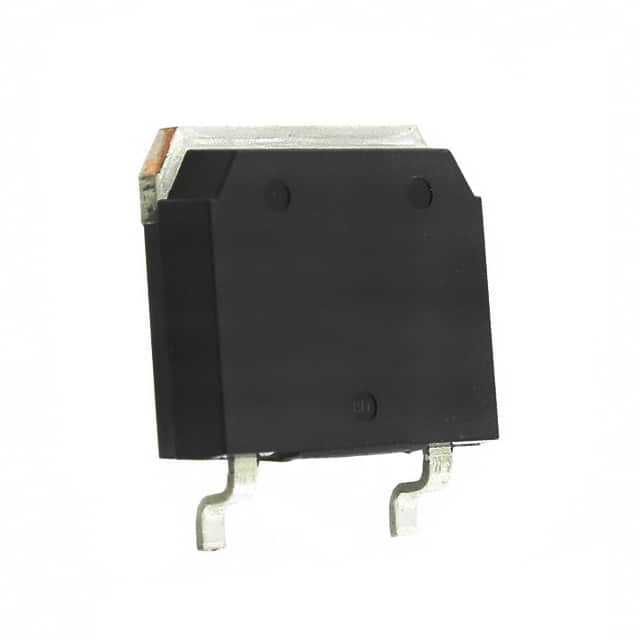
- Package: TO-268
- Essence: IXGT30N120BD1 is a high-voltage IGBT (Insulated Gate Bipolar Transistor) designed for power electronic applications.
- Packaging/Quantity: Typically packaged in reels of 500 units.
Specifications
- Voltage Rating: 1200V
- Current Rating: 60A
- Switching Speed: <100ns
- Maximum Operating Temperature: 150°C
- Gate-Emitter Voltage: ±20V
Detailed Pin Configuration
The IXGT30N120BD1 has a standard TO-268 package with three pins: 1. Collector (C) 2. Gate (G) 3. Emitter (E)
Functional Features
- High voltage capability
- Low saturation voltage
- Fast switching speed
- Low tail current
- Positive temperature coefficient for easy paralleling
Advantages and Disadvantages
Advantages
- High voltage and current ratings
- Fast switching speed
- Low saturation voltage
- Positive temperature coefficient
Disadvantages
- Higher cost compared to traditional power diodes
- Requires careful handling due to sensitivity to static electricity
Working Principles
The IXGT30N120BD1 operates based on the principles of an Insulated Gate Bipolar Transistor. When a positive voltage is applied to the gate terminal, it allows current to flow between the collector and emitter terminals. The fast switching speed and low saturation voltage make it suitable for high-power switching applications.
Detailed Application Field Plans
The IXGT30N120BD1 is commonly used in various high-power applications such as: - Motor drives - Uninterruptible power supplies (UPS) - Renewable energy systems - Induction heating - Welding equipment
Detailed and Complete Alternative Models
Some alternative models to IXGT30N120BD1 include: - IRGP4063DPBF - FGA60N65SMD - STGW40NC60WD
In conclusion, the IXGT30N120BD1 is a high-voltage IGBT with fast switching characteristics, making it suitable for various high-power applications. Its advantages include high voltage and current ratings, while its disadvantages include higher cost and sensitivity to static electricity. It finds extensive use in motor drives, UPS, renewable energy systems, induction heating, and welding equipment.
[Word Count: 346]
Liệt kê 10 câu hỏi và câu trả lời thường gặp liên quan đến ứng dụng IXGT30N120BD1 trong giải pháp kỹ thuật
What is the maximum voltage rating of IXGT30N120BD1?
- The maximum voltage rating of IXGT30N120BD1 is 1200V.
What is the maximum current rating of IXGT30N120BD1?
- The maximum current rating of IXGT30N120BD1 is 30A.
What type of package does IXGT30N120BD1 come in?
- IXGT30N120BD1 comes in a TO-268 package.
What are the typical applications for IXGT30N120BD1?
- IXGT30N120BD1 is commonly used in applications such as motor drives, inverters, and power supplies.
Does IXGT30N120BD1 have built-in protection features?
- Yes, IXGT30N120BD1 has built-in overcurrent and overtemperature protection features.
What is the on-state voltage drop of IXGT30N120BD1?
- The on-state voltage drop of IXGT30N120BD1 is typically around 1.8V at 15A.
Is IXGT30N120BD1 suitable for high-frequency switching applications?
- Yes, IXGT30N120BD1 is suitable for high-frequency switching due to its fast switching characteristics.
What is the thermal resistance of IXGT30N120BD1?
- The thermal resistance of IXGT30N120BD1 is typically around 0.5°C/W.
Can IXGT30N120BD1 be used in parallel configurations for higher current applications?
- Yes, IXGT30N120BD1 can be used in parallel configurations to achieve higher current ratings.
Are there any specific layout considerations when using IXGT30N120BD1 in a circuit?
- It is recommended to minimize loop inductance and provide adequate thermal management when designing circuits with IXGT30N120BD1.