

Xem thông số kỹ thuật để biết chi tiết sản phẩm.
MAX4525EUB+ - English Editing Encyclopedia Entry
Product Overview
Category: Integrated Circuit (IC)
Use: The MAX4525EUB+ is a high-performance, low-voltage, single-supply, dual SPST (Single-Pole Single-Throw) analog switch. It is designed for use in various applications that require signal routing and switching.
Characteristics: - High performance: The MAX4525EUB+ offers low on-resistance and low leakage current, ensuring minimal signal distortion and accurate switching. - Low-voltage operation: It operates at a low voltage range of 1.8V to 5.5V, making it suitable for battery-powered devices and low-power applications. - Single-supply operation: The IC can be powered by a single supply voltage, simplifying the circuit design and reducing component count. - Dual SPST configuration: The MAX4525EUB+ consists of two independent Single-Pole Single-Throw switches, allowing for versatile signal routing options. - ESD protection: It provides built-in electrostatic discharge (ESD) protection, safeguarding the IC from potential damage during handling and operation.
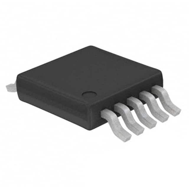
Package: The MAX4525EUB+ is available in a small-sized µMAX package, which is a space-saving 10-pin micro lead frame (MLF) package.
Essence: The essence of the MAX4525EUB+ lies in its ability to provide reliable and efficient signal switching capabilities in a compact form factor, suitable for a wide range of applications.
Packaging/Quantity: The MAX4525EUB+ is typically sold in reels or tubes, with a quantity of 250 units per reel/tube.
Specifications
- Supply Voltage Range: 1.8V to 5.5V
- On-Resistance (RON): 0.4Ω (typical)
- Leakage Current (ILEAK): 0.1nA (typical)
- Bandwidth: DC to 50MHz
- Crosstalk Rejection: -80dB (typical)
- ESD Protection: ±15kV (Human Body Model)
Pin Configuration
The MAX4525EUB+ features the following pin configuration:
```
| | --| IN1 OUT1 |-- --| GND VCC |-- --| IN2 OUT2 |-- |___________| ```
Pin Description: - IN1, IN2: Input pins for controlling the switch state. - OUT1, OUT2: Output pins for the switched signal. - GND: Ground connection. - VCC: Supply voltage input.
Functional Features
The key functional features of the MAX4525EUB+ include: 1. Dual SPST Switches: The IC provides two independent Single-Pole Single-Throw switches, enabling flexible signal routing and switching options. 2. Low On-Resistance: With a typical on-resistance of 0.4Ω, the MAX4525EUB+ ensures minimal signal attenuation and distortion during switching. 3. Low Leakage Current: The IC exhibits a low leakage current of 0.1nA, reducing power consumption and maintaining signal integrity. 4. Wide Voltage Range: It operates within a wide supply voltage range of 1.8V to 5.5V, accommodating various system requirements. 5. High Bandwidth: The MAX4525EUB+ supports a bandwidth of up to 50MHz, making it suitable for high-frequency applications. 6. ESD Protection: Built-in electrostatic discharge protection safeguards the IC from potential damage caused by static electricity.
Advantages and Disadvantages
Advantages: - High-performance signal switching with low on-resistance and leakage current. - Wide supply voltage range allows compatibility with different power sources. - Compact package size saves board space. - ESD protection ensures reliability in handling and operation.
Disadvantages: - Limited to dual SPST configuration, may not be suitable for applications requiring multiple switch configurations. - Higher cost compared to basic analog switches due to enhanced performance features.
Working Principles
The MAX4525EUB+ operates based on the principles of solid-state switching. When the control input (IN1 or IN2) is activated, the corresponding switch (OUT1 or OUT2) connects the input signal to the output terminal. The low on-resistance and low leakage current characteristics ensure minimal signal distortion during the switching process.
Application Field Plans
The MAX4525EUB+ finds application in various fields, including: 1. Audio/Video Signal Routing: It can be used in audio/video systems to route signals between different sources and destinations. 2. Test and Measurement Equipment: The IC enables signal switching in test and measurement setups, allowing for flexible signal routing and analysis.
Liệt kê 10 câu hỏi và câu trả lời thường gặp liên quan đến ứng dụng MAX4525EUB+ trong giải pháp kỹ thuật
Sure! Here are 10 common questions and answers related to the application of MAX4525EUB+ in technical solutions:
Q: What is the MAX4525EUB+? A: The MAX4525EUB+ is a precision, dual, single-pole/single-throw (SPST) analog switch that can be used for various applications.
Q: What is the maximum voltage rating of the MAX4525EUB+? A: The MAX4525EUB+ has a maximum voltage rating of ±22V.
Q: Can the MAX4525EUB+ handle both AC and DC signals? A: Yes, the MAX4525EUB+ can handle both AC and DC signals.
Q: What is the on-resistance of the MAX4525EUB+? A: The on-resistance of the MAX4525EUB+ is typically 50 ohms.
Q: What is the operating temperature range of the MAX4525EUB+? A: The MAX4525EUB+ can operate within a temperature range of -40°C to +85°C.
Q: Can the MAX4525EUB+ be used in battery-powered applications? A: Yes, the low power consumption of the MAX4525EUB+ makes it suitable for battery-powered applications.
Q: Does the MAX4525EUB+ have built-in protection against overvoltage? A: No, the MAX4525EUB+ does not have built-in overvoltage protection. External protection circuitry may be required.
Q: Can I use the MAX4525EUB+ in audio switching applications? A: Yes, the low distortion and high signal integrity of the MAX4525EUB+ make it suitable for audio switching applications.
Q: What is the supply voltage range for the MAX4525EUB+? A: The supply voltage range for the MAX4525EUB+ is typically between ±4V and ±18V.
Q: Can I use multiple MAX4525EUB+ devices in parallel to increase the number of channels? A: Yes, multiple MAX4525EUB+ devices can be used in parallel to increase the number of channels in a system.
Please note that these answers are general and may vary depending on specific application requirements. It is always recommended to refer to the datasheet and consult with the manufacturer for detailed information.