

Xem thông số kỹ thuật để biết chi tiết sản phẩm.
PIC16F57-I/SP
Product Overview
Category
The PIC16F57-I/SP belongs to the category of microcontrollers.
Use
This microcontroller is commonly used in various electronic devices and systems for controlling and processing data.
Characteristics
- Low power consumption
- High-performance RISC CPU
- Wide operating voltage range
- Flash program memory
- EEPROM data memory
- I/O ports with programmable pull-ups
- Timers and counters
- Analog-to-digital converter (ADC)
- Serial communication interface
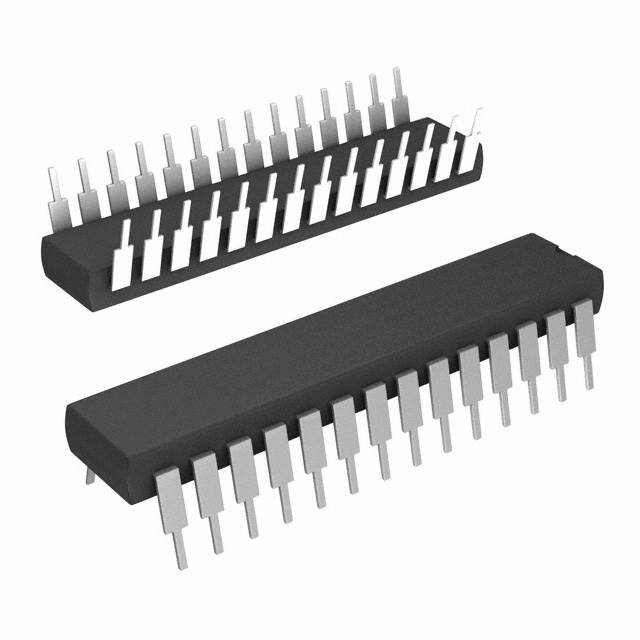
Package
The PIC16F57-I/SP is available in a 28-pin plastic dual inline package (DIP).
Essence
The essence of the PIC16F57-I/SP lies in its ability to provide a cost-effective solution for embedded control applications.
Packaging/Quantity
This microcontroller is typically packaged in tubes or trays, with quantities varying based on customer requirements.
Specifications
- CPU: 8-bit RISC
- Program Memory: 3.5 KB Flash
- Data Memory: 128 bytes EEPROM
- Operating Voltage Range: 2.0V to 5.5V
- I/O Pins: 22
- Timers: 1 x 8-bit, 1 x 16-bit
- ADC: 5 channels, 10-bit resolution
- Communication Interfaces: USART, SPI, I2C
Detailed Pin Configuration
The PIC16F57-I/SP has a total of 28 pins, each serving a specific purpose. The pin configuration is as follows:
- VDD - Power supply voltage
- RA0/AN0 - Analog input channel 0 / Digital I/O pin
- RA1/AN1 - Analog input channel 1 / Digital I/O pin
- RA2/AN2 - Analog input channel 2 / Digital I/O pin
- RA3/AN3 - Analog input channel 3 / Digital I/O pin
- RA4/T0CKI/C1OUT - Timer0 clock input / Digital I/O pin / Comparator output
- MCLR/VPP - Master Clear input / Programming voltage
- VSS - Ground
- RB0/INT - External interrupt input / Digital I/O pin
- RB1/SDI/SDA - SPI data input / I2C data input
- RB2/SDO/SCL - SPI data output / I2C clock
- RB3/PGM - Programming mode select
- RB4/PGC - Programming clock
- RB5/PGD - Programming data
- RB6/OSC1/CLKIN - Oscillator input
- RB7/OSC2/CLKOUT - Oscillator output
- RC0/T1OSO/T1CKI - Timer1 oscillator output / Timer1 clock input
- RC1/T1OSI/CCP2 - Timer1 oscillator input / CCP2 module
- RC2/CCP1 - CCP1 module
- RC3/SCK/SCL - SPI/I2C clock
- RC4/SDO/SDA - SPI data output / I2C data output
- RC5/SDI - SPI data input
- RC6/TX/CK - USART transmit / Clock
- RC7/RX/DT - USART receive / Data
- VDD - Power supply voltage
- VSS - Ground
- OSC1/CLKIN - Oscillator input
- OSC2/CLKOUT - Oscillator output
Functional Features
The PIC16F57-I/SP offers several functional features that enhance its usability and performance. These include:
- Flash program memory for storing the application code
- EEPROM data memory for non-volatile storage
- I/O ports with programmable pull-ups for easy interfacing with external devices
- Timers and counters for precise timing operations
- Analog-to-digital converter (ADC) for converting analog signals to digital values
- Serial communication interfaces (USART, SPI, I2C) for data exchange with other devices
Advantages and Disadvantages
Advantages
- Low power consumption makes it suitable for battery-powered applications
- High-performance RISC CPU enables efficient execution of instructions
- Wide operating voltage range allows flexibility in different power supply scenarios
- Ample program and data memory for most embedded control applications
- Versatile I/O capabilities facilitate connectivity with external components
Disadvantages
- Limited number of I/O pins may restrict the complexity of certain projects
- Lack of advanced features found in more advanced microcontrollers
- Relatively small program memory size compared to some competitors
Working Principles
The PIC16F57-I/SP operates based on the principles of a RISC
Liệt kê 10 câu hỏi và câu trả lời thường gặp liên quan đến ứng dụng PIC16F57-I/SP trong giải pháp kỹ thuật
What is the maximum clock frequency of PIC16F57-I/SP?
- The maximum clock frequency of PIC16F57-I/SP is 20 MHz.Can PIC16F57-I/SP be used for analog signal processing?
- Yes, PIC16F57-I/SP has built-in analog-to-digital converters and can be used for analog signal processing.What are the available communication interfaces on PIC16F57-I/SP?
- PIC16F57-I/SP supports serial communication interfaces such as SPI and I2C.Is it possible to program PIC16F57-I/SP using C language?
- Yes, PIC16F57-I/SP can be programmed using C language with appropriate compilers and development tools.What are the available timer modules in PIC16F57-I/SP?
- PIC16F57-I/SP features multiple timer modules including Timer0, Timer1, and Timer2.Can PIC16F57-I/SP operate in low power modes?
- Yes, PIC16F57-I/SP offers various low power modes to conserve energy.Does PIC16F57-I/SP have built-in EEPROM memory?
- No, PIC16F57-I/SP does not have built-in EEPROM memory.What are the available I/O pins on PIC16F57-I/SP?
- PIC16F57-I/SP provides a range of digital and analog I/O pins for interfacing with external devices.Is PIC16F57-I/SP suitable for battery-powered applications?
- Yes, PIC16F57-I/SP's low power modes make it suitable for battery-powered applications.Can PIC16F57-I/SP be used in automotive electronics?
- Yes, PIC16F57-I/SP is suitable for automotive electronics applications due to its robust design and wide operating temperature range.