

Xem thông số kỹ thuật để biết chi tiết sản phẩm.
PIC18LF24J50-I/SO
Product Overview
- Category: Microcontroller
- Use: Embedded systems, Internet of Things (IoT) devices, consumer electronics
- Characteristics: Low power consumption, high performance, versatile functionality
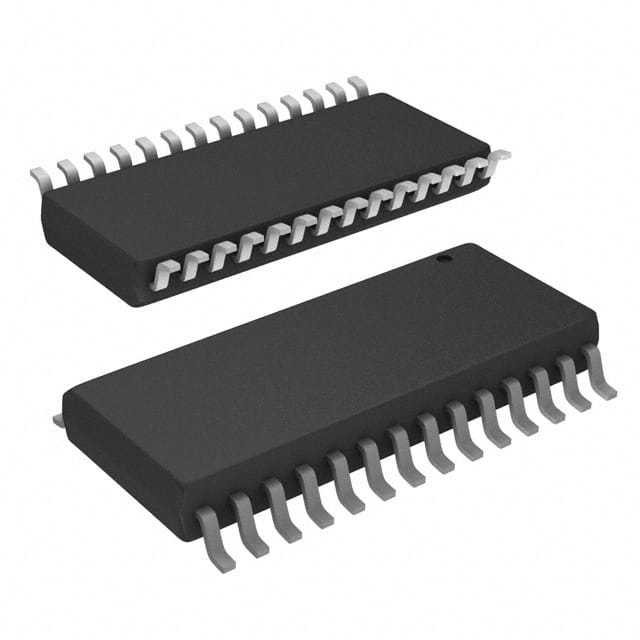
- Package: SOIC (Small Outline Integrated Circuit)
- Essence: A powerful microcontroller designed for various applications requiring low power and high performance.
- Packaging/Quantity: Available in tape and reel packaging, with a quantity of 250 units per reel.
Specifications
- Architecture: 8-bit
- Flash Memory: 24KB
- RAM: 2KB
- Operating Voltage: 2.3V to 5.5V
- Operating Temperature Range: -40°C to +85°C
- Number of I/O Pins: 20
- Communication Interfaces: SPI, I2C, UART
- Analog-to-Digital Converter (ADC): 10-bit, 13 channels
- Timers: 4 x 8-bit, 1 x 16-bit
- PWM Channels: 5
- Clock Speed: Up to 48 MHz
Detailed Pin Configuration
The PIC18LF24J50-I/SO microcontroller has a total of 20 pins, which are assigned for various functions such as I/O, power supply, communication, and programming. The pin configuration is as follows:
- VDD - Power Supply
- RA0/AN0 - Analog Input/Output or Digital I/O
- RA1/AN1 - Analog Input/Output or Digital I/O
- RA2/AN2 - Analog Input/Output or Digital I/O
- RA3/AN3/VREF-/CVREF - Analog Input/Output or Digital I/O
- RA4/T0CKI/C1OUT - Timer0 Clock Input or Digital I/O
- VSS - Ground
- RA5/AN4/SS/HLVDIN - Analog Input/Output, Slave Select or High/Low Voltage Detect Input
- RE0/INT0/FLTA/CCP2 - External Interrupt 0, Fault Input A or Capture/Compare/PWM 2
- RE1/INT1/FLTB/CCP3 - External Interrupt 1, Fault Input B or Capture/Compare/PWM 3
- RE2/INT2/VMO/CCP4 - External Interrupt 2, Voltage Monitor Output or Capture/Compare/PWM 4
- VUSB - USB Power Supply
- RB0/PGM/CCP1 - Programming/Data Memory Interface or Capture/Compare/PWM 1
- RB1/PGC/CCP5 - Programming/Debug Clock or Capture/Compare/PWM 5
- RB2/PGD - Programming/Debug Data
- RB3/SCL/SCK - I2C Serial Clock or SPI Serial Clock
- RB4/SDA/SDI - I2C Serial Data or SPI Serial Data Input
- RB5/SDO - SPI Serial Data Output
- RB6/PGM - Programming/Data Memory Interface
- RB7/PGC - Programming/Debug Clock
Functional Features
- Low power consumption: The PIC18LF24J50-I/SO microcontroller is designed to operate efficiently with low power requirements, making it suitable for battery-powered devices.
- High performance: With a clock speed of up to 48 MHz and a powerful 8-bit architecture, this microcontroller offers fast and reliable processing capabilities.
- Versatile functionality: It supports various communication interfaces such as SPI, I2C, and UART, enabling seamless integration with other devices.
- Analog-to-Digital Converter (ADC): The built-in 10-bit ADC allows for accurate analog signal measurements and conversions.
- Timers and PWM Channels: Multiple timers and PWM channels provide precise timing control and enable the generation of analog-like signals.
Advantages and Disadvantages
Advantages
- Low power consumption extends battery life in portable applications.
- Versatile functionality allows for flexible system design and integration.
- High-performance processing capabilities enable efficient execution of complex tasks.
- Built-in ADC simplifies analog signal processing.
- Ample I/O pins provide flexibility for connecting external devices.
Disadvantages
- Limited flash memory capacity may restrict the size of the firmware or program that can be stored.
- The 8-bit architecture may not be suitable for applications requiring extensive computational power.
- Lack of built-in Ethernet or Wi-Fi connectivity may require additional components for networking capabilities.
Working Principles
The PIC18LF24J50-I/SO microcontroller operates based on the Harvard architecture, which separates program memory and data memory. It executes
Liệt kê 10 câu hỏi và câu trả lời thường gặp liên quan đến ứng dụng PIC18LF24J50-I/SO trong giải pháp kỹ thuật
What is the maximum operating frequency of PIC18LF24J50-I/SO?
- The maximum operating frequency of PIC18LF24J50-I/SO is 32 MHz.Can PIC18LF24J50-I/SO be used in battery-powered applications?
- Yes, PIC18LF24J50-I/SO is suitable for battery-powered applications due to its low power consumption.What are the communication interfaces supported by PIC18LF24J50-I/SO?
- PIC18LF24J50-I/SO supports SPI, I2C, and UART communication interfaces.Is PIC18LF24J50-I/SO compatible with 5V systems?
- No, PIC18LF24J50-I/SO operates at a maximum voltage of 3.6V and is not directly compatible with 5V systems.Can PIC18LF24J50-I/SO be used for USB connectivity?
- Yes, PIC18LF24J50-I/SO features USB 2.0 support for connectivity.What development tools are available for programming PIC18LF24J50-I/SO?
- Development tools such as MPLAB X IDE and PICkit programmers can be used for programming PIC18LF24J50-I/SO.Does PIC18LF24J50-I/SO have built-in analog-to-digital converters (ADC)?
- Yes, PIC18LF24J50-I/SO has integrated 10-bit ADC modules.What is the flash memory size of PIC18LF24J50-I/SO?
- PIC18LF24J50-I/SO has 16 KB of flash memory for program storage.Can PIC18LF24J50-I/SO be used in industrial control applications?
- Yes, PIC18LF24J50-I/SO is suitable for industrial control applications due to its robust features and peripherals.Are there any application notes or reference designs available for PIC18LF24J50-I/SO?
- Yes, Microchip provides application notes and reference designs for implementing PIC18LF24J50-I/SO in various technical solutions.