

Xem thông số kỹ thuật để biết chi tiết sản phẩm.
Encyclopedia Entry: 74AUP1G18GM,115
Product Overview
Category
The 74AUP1G18GM,115 belongs to the category of integrated circuits (ICs).
Use
This product is commonly used in electronic devices for signal switching and amplification.
Characteristics
- Low power consumption
- High-speed operation
- Small form factor
- Wide operating voltage range
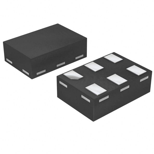
Package
The 74AUP1G18GM,115 is available in a small package, typically a SOT-353 or SC-88A.
Essence
The essence of this product lies in its ability to provide efficient signal switching and amplification in a compact design.
Packaging/Quantity
The 74AUP1G18GM,115 is usually packaged in reels or tubes, with quantities varying depending on the manufacturer's specifications.
Specifications
- Supply Voltage Range: 0.8V to 3.6V
- Input Voltage Range: -0.5V to VCC + 0.5V
- Output Voltage Range: -0.5V to VCC + 0.5V
- Operating Temperature Range: -40°C to +85°C
- Maximum Power Dissipation: 150mW
Detailed Pin Configuration
The 74AUP1G18GM,115 has the following pin configuration:
```
| | --| A | --| Y | --| GND | --| VCC | |___________| ```
Functional Features
- Single input AND gate functionality
- High-speed operation allows for quick signal processing
- Low power consumption makes it suitable for battery-powered devices
- Wide operating voltage range ensures compatibility with various systems
Advantages and Disadvantages
Advantages
- Compact size enables integration into space-constrained designs
- Low power consumption prolongs battery life in portable devices
- High-speed operation allows for efficient signal processing
Disadvantages
- Limited number of input/output pins restricts complex circuit design possibilities
- Sensitivity to electrostatic discharge (ESD) requires proper handling during assembly and usage
Working Principles
The 74AUP1G18GM,115 operates based on the principles of digital logic. It utilizes an AND gate configuration to process input signals and generate the corresponding output signal. The internal circuitry ensures reliable and accurate signal switching and amplification.
Detailed Application Field Plans
The 74AUP1G18GM,115 finds applications in various electronic systems, including but not limited to: - Mobile phones - Tablets - Portable media players - Wearable devices - Automotive electronics - Industrial control systems
Detailed and Complete Alternative Models
Some alternative models that offer similar functionality to the 74AUP1G18GM,115 include: - 74LVC1G08GW,125 - SN74LVC1G08DBVR - MC74VHC1G08DTT1G
These alternatives can be considered based on specific requirements and availability.
In conclusion, the 74AUP1G18GM,115 is a compact and efficient integrated circuit used for signal switching and amplification. Its low power consumption, high-speed operation, and wide operating voltage range make it suitable for various electronic applications. However, its limited pin count and sensitivity to ESD should be taken into consideration during design and usage.
Liệt kê 10 câu hỏi và câu trả lời thường gặp liên quan đến ứng dụng 74AUP1G18GM,115 trong giải pháp kỹ thuật
Sure! Here are 10 common questions and answers related to the application of 74AUP1G18GM,115 in technical solutions:
Q1: What is the function of the 74AUP1G18GM,115? A1: The 74AUP1G18GM,115 is a single AND gate that can be used for logic level conversion or signal conditioning.
Q2: What is the operating voltage range of the 74AUP1G18GM,115? A2: The 74AUP1G18GM,115 operates within a voltage range of 0.8V to 3.6V.
Q3: Can the 74AUP1G18GM,115 handle high-speed signals? A3: Yes, the 74AUP1G18GM,115 is designed to handle high-speed signals with a maximum propagation delay of 2.5 ns.
Q4: How many inputs does the 74AUP1G18GM,115 have? A4: The 74AUP1G18GM,115 has one input pin.
Q5: What is the output drive capability of the 74AUP1G18GM,115? A5: The 74AUP1G18GM,115 has a typical output drive capability of 32 mA.
Q6: Can the 74AUP1G18GM,115 be used in battery-powered applications? A6: Yes, the 74AUP1G18GM,115 is suitable for battery-powered applications due to its low power consumption.
Q7: Is the 74AUP1G18GM,115 compatible with other logic families? A7: Yes, the 74AUP1G18GM,115 is compatible with various logic families such as CMOS, TTL, and LVCMOS.
Q8: Can the 74AUP1G18GM,115 be used in both digital and analog applications? A8: No, the 74AUP1G18GM,115 is primarily designed for digital applications and may not be suitable for analog applications.
Q9: What is the package type of the 74AUP1G18GM,115? A9: The 74AUP1G18GM,115 is available in a small SOT353 package.
Q10: Are there any recommended operating conditions for the 74AUP1G18GM,115? A10: Yes, some recommended operating conditions include a supply voltage between 0.8V and 3.6V, an ambient temperature range of -40°C to +125°C, and a maximum input voltage of VCC + 0.5V.
Please note that these answers are general and it's always recommended to refer to the datasheet or consult the manufacturer for specific details and guidelines related to the application of the 74AUP1G18GM,115 in your technical solution.