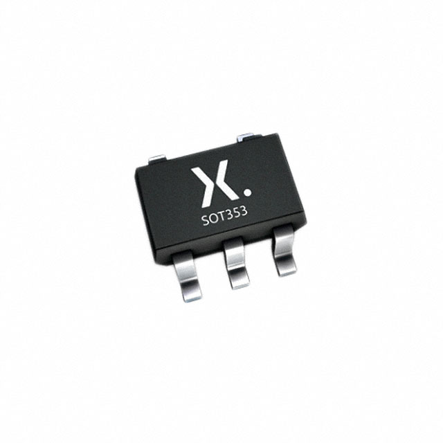
Xem thông số kỹ thuật để biết chi tiết sản phẩm.

74LVC1GU04GW,125
Basic Information Overview
- Category: Integrated Circuit (IC)
- Use: Logic Gate Inverter
- Characteristics: Low-voltage CMOS technology, high-speed operation, low power consumption
- Package: SOT753 (SC-70)
- Essence: Single gate inverter
- Packaging/Quantity: Tape and Reel, 3000 pieces per reel
Specifications
- Supply Voltage Range: 1.65V to 5.5V
- Input Voltage Range: 0V to VCC
- Output Voltage Range: 0V to VCC
- Maximum Operating Frequency: 500 MHz
- Propagation Delay: 3.8 ns (typical) at 3.3V supply voltage
- Input Capacitance: 2 pF (typical)
- Output Drive Capability: ±24 mA
Detailed Pin Configuration
The 74LVC1GU04GW,125 has a total of 5 pins: 1. GND (Ground): Connected to the ground reference. 2. IN (Input): Accepts the input logic signal. 3. VCC (Power Supply): Connected to the positive supply voltage. 4. OUT (Output): Provides the inverted output logic signal. 5. NC (No Connection): This pin is not connected and should be left unconnected.
Functional Features
- Single gate inverter with Schmitt-trigger input
- Converts logic levels from one polarity to the opposite polarity
- High-speed operation allows for efficient signal processing
- Low power consumption makes it suitable for battery-powered devices
- Wide supply voltage range enables compatibility with various systems
Advantages and Disadvantages
Advantages: - Compact size due to single gate design - High-speed operation for quick signal inversion - Low power consumption extends battery life - Wide supply voltage range enhances versatility
Disadvantages: - Limited drive capability compared to some other ICs - Only provides a single logic function (inversion)
Working Principles
The 74LVC1GU04GW,125 is based on low-voltage CMOS technology. It utilizes a single gate inverter with a Schmitt-trigger input. When an input logic signal is applied, the inverter converts the logic level from one polarity to the opposite polarity at the output. This inversion is achieved through the use of complementary metal-oxide-semiconductor (CMOS) transistors.
Detailed Application Field Plans
The 74LVC1GU04GW,125 can be used in various applications, including but not limited to: - Digital logic circuits - Signal level shifting - Voltage level conversion - Clock signal inversion - Sensor interfaces - Battery-powered devices
Detailed and Complete Alternative Models
Some alternative models that provide similar functionality to the 74LVC1GU04GW,125 include: - SN74LVC1G04DBVR (Texas Instruments) - MC74VHC1GU04DTT1G (ON Semiconductor) - NC7SZ04P5X (Fairchild Semiconductor) - TC7SZ04FU (Toshiba)
Note: The above list is not exhaustive and there may be other alternative models available in the market.
This entry provides an overview of the 74LVC1GU04GW,125 integrated circuit. It includes basic information about its category, use, characteristics, package, and essence. The specifications, pin configuration, functional features, advantages and disadvantages, working principles, application field plans, and alternative models are also discussed.
Liệt kê 10 câu hỏi và câu trả lời thường gặp liên quan đến ứng dụng 74LVC1GU04GW,125 trong giải pháp kỹ thuật
Sure! Here are 10 common questions and answers related to the application of 74LVC1GU04GW,125:
Q1: What is the 74LVC1GU04GW,125? A1: The 74LVC1GU04GW,125 is a single inverter gate IC (Integrated Circuit) that is commonly used in digital logic circuits.
Q2: What is the operating voltage range for the 74LVC1GU04GW,125? A2: The operating voltage range for the 74LVC1GU04GW,125 is typically between 1.65V and 5.5V.
Q3: What is the maximum output current of the 74LVC1GU04GW,125? A3: The maximum output current of the 74LVC1GU04GW,125 is around 32mA.
Q4: Can the 74LVC1GU04GW,125 be used as a level shifter? A4: Yes, the 74LVC1GU04GW,125 can be used as a level shifter to convert signals from one voltage level to another.
Q5: What is the propagation delay of the 74LVC1GU04GW,125? A5: The propagation delay of the 74LVC1GU04GW,125 is typically around 4.3ns.
Q6: Is the 74LVC1GU04GW,125 suitable for high-speed applications? A6: Yes, the 74LVC1GU04GW,125 is designed for high-speed operation and can be used in various high-frequency applications.
Q7: Can the 74LVC1GU04GW,125 drive capacitive loads? A7: Yes, the 74LVC1GU04GW,125 can drive small capacitive loads without any additional buffering.
Q8: What is the power supply current consumption of the 74LVC1GU04GW,125? A8: The power supply current consumption of the 74LVC1GU04GW,125 is typically very low, making it suitable for low-power applications.
Q9: Can the 74LVC1GU04GW,125 be used in both CMOS and TTL logic systems? A9: Yes, the 74LVC1GU04GW,125 is compatible with both CMOS and TTL logic levels, allowing it to be used in a wide range of systems.
Q10: Are there any specific precautions to consider when using the 74LVC1GU04GW,125? A10: It is important to ensure that the input voltage does not exceed the specified maximum voltage, and to avoid exceeding the maximum output current to prevent damage to the IC. Additionally, proper decoupling capacitors should be used to minimize noise and stabilize the power supply.

