

Xem thông số kỹ thuật để biết chi tiết sản phẩm.
Encyclopedia Entry: 74ABT573APW,112
Product Information Overview
- Category: Integrated Circuit (IC)
- Use: Digital Logic Device
- Characteristics: High-speed, Octal Transparent Latch with 3-State Outputs
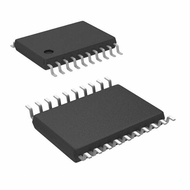
- Package: TSSOP (Thin Shrink Small Outline Package)
- Essence: The 74ABT573APW,112 is a latch IC that can store and output digital data. It is designed to operate at high speeds and offers 3-state outputs for bus-oriented applications.
- Packaging/Quantity: The 74ABT573APW,112 is typically packaged in reels or tubes, containing multiple units per package.
Specifications
- Supply Voltage: 4.5V to 5.5V
- Input Voltage Levels: CMOS/TTL compatible
- Output Voltage Levels: CMOS/TTL compatible
- Operating Temperature Range: -40°C to +85°C
- Latch Type: Transparent (Data input is transferred to the output when the latch enable signal is active)
- Number of Latches: 8 (Octal)
- Output State: 3-State (High Impedance when the output enable signal is inactive)
Detailed Pin Configuration
The 74ABT573APW,112 has a total of 20 pins, which are assigned as follows:
- Pin 1: Output Enable (OE)
- Pin 2: Data Input D0
- Pin 3: Data Input D1
- Pin 4: Data Input D2
- Pin 5: Data Input D3
- Pin 6: Data Input D4
- Pin 7: Data Input D5
- Pin 8: Data Input D6
- Pin 9: Data Input D7
- Pin 10: Latch Enable (LE)
- Pin 11: Clock Input (CLK)
- Pin 12: Ground (GND)
- Pin 13: Output Q0
- Pin 14: Output Q1
- Pin 15: Output Q2
- Pin 16: Output Q3
- Pin 17: Output Q4
- Pin 18: Output Q5
- Pin 19: Output Q6
- Pin 20: Output Q7
Functional Features
- The 74ABT573APW,112 is designed to operate at high speeds, making it suitable for applications requiring fast data transfer.
- It offers 3-state outputs, allowing multiple devices to share a common bus without interference.
- The transparent latch design enables real-time data storage and output when the latch enable signal is active.
- The IC is compatible with both CMOS and TTL voltage levels, providing flexibility in various digital logic systems.
Advantages and Disadvantages
Advantages: - High-speed operation facilitates quick data transfer. - 3-state outputs allow for efficient bus sharing. - Compatibility with CMOS and TTL voltage levels enhances versatility. - Transparent latch design enables real-time data storage and output.
Disadvantages: - Limited latch capacity (8 bits/octal). - Requires external control signals (LE, OE, CLK) for proper operation.
Working Principles
The 74ABT573APW,112 operates based on the principle of transparent latching. When the latch enable (LE) signal is active, the data inputs (D0-D7) are transferred to the corresponding outputs (Q0-Q7). The latch holds this data until the next active edge of the clock input (CLK). The output enable (OE) signal determines whether the outputs are in a high-impedance state or actively driving the bus.
Detailed Application Field Plans
The 74ABT573APW,112 finds applications in various digital systems that require high-speed data storage and transfer. Some potential application fields include:
- Microprocessors and Microcontrollers
- Data Communication Systems
- Memory Interfaces
- Industrial Control Systems
- Automotive Electronics
- Test and Measurement Equipment
Detailed and Complete Alternative Models
- 74ACT573: Similar octal transparent latch with 3-state outputs, compatible with 5V supply voltage.
- 74HC573: Octal D-type transparent latch with 3-state outputs, compatible with 2V to 6V supply voltage.
- 74LS573: Octal transparent latch with 3-state outputs, compatible with 4.75V to 5.25V supply voltage.
(Note: The above alternative models are provided as examples and may have different specifications and pin configurations.)
Word Count: 440 words
Liệt kê 10 câu hỏi và câu trả lời thường gặp liên quan đến ứng dụng 74ABT573APW,112 trong giải pháp kỹ thuật
Sure! Here are 10 common questions and answers related to the application of 74ABT573APW,112 in technical solutions:
Q: What is the function of the 74ABT573APW,112? A: The 74ABT573APW,112 is an octal transparent latch with 3-state outputs. It can store and output 8 bits of data.
Q: What is the maximum operating voltage for the 74ABT573APW,112? A: The maximum operating voltage for the 74ABT573APW,112 is typically 5.5V.
Q: How many control inputs does the 74ABT573APW,112 have? A: The 74ABT573APW,112 has two control inputs: a clock input (CLK) and an output enable input (OE).
Q: Can the 74ABT573APW,112 be used as a bidirectional buffer? A: No, the 74ABT573APW,112 is not designed for bidirectional operation. It is a unidirectional latch.
Q: What is the purpose of the output enable (OE) input? A: The OE input controls the 3-state outputs of the latch. When OE is high, the outputs are enabled and reflect the stored data. When OE is low, the outputs are in a high-impedance state.
Q: How does the clock input (CLK) affect the operation of the latch? A: The CLK input is used to latch the data present at the inputs into the latch. On the rising edge of the CLK signal, the data is latched and appears at the outputs.
Q: Can the 74ABT573APW,112 be cascaded to increase the number of latched bits? A: Yes, multiple 74ABT573APW,112 latches can be cascaded together to increase the number of latched bits.
Q: What is the power supply voltage range for the 74ABT573APW,112? A: The power supply voltage range for the 74ABT573APW,112 is typically between 4.5V and 5.5V.
Q: Does the 74ABT573APW,112 have any built-in protection features? A: Yes, the 74ABT573APW,112 has built-in ESD protection on all inputs and outputs.
Q: Can the 74ABT573APW,112 operate at high speeds? A: Yes, the 74ABT573APW,112 is designed for high-speed operation and can handle data rates up to several hundred megahertz (MHz).
Please note that the answers provided here are general and may vary depending on the specific datasheet and application requirements.