

Xem thông số kỹ thuật để biết chi tiết sản phẩm.
Encyclopedia Entry: 74ALVC16245DTR
Product Overview
Category
The 74ALVC16245DTR belongs to the category of integrated circuits (ICs).
Use
This IC is commonly used for signal transmission and buffering in digital electronic systems.
Characteristics
- High-speed operation
- Low power consumption
- Wide operating voltage range
- Bidirectional data flow capability
- ESD protection on all inputs and outputs
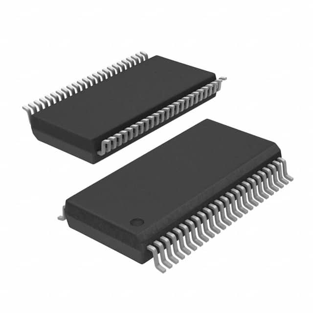
Package
The 74ALVC16245DTR is available in a TSSOP package, which stands for Thin Shrink Small Outline Package. This package offers a compact size and good thermal performance.
Essence
The essence of the 74ALVC16245DTR lies in its ability to efficiently transmit and buffer digital signals while consuming minimal power.
Packaging/Quantity
The 74ALVC16245DTR is typically packaged in reels or tubes, with a quantity of 2500 units per reel/tube.
Specifications
- Supply Voltage Range: 1.2V to 3.6V
- Input Voltage Range: -0.5V to VCC + 0.5V
- Output Voltage Range: -0.5V to VCC + 0.5V
- Operating Temperature Range: -40°C to +85°C
- Maximum Propagation Delay: 4.5ns (typical)
- Maximum Output Current: ±24mA
Detailed Pin Configuration
The 74ALVC16245DTR has a total of 48 pins, arranged as follows:
Pin Configuration Diagram
      ___________________________
     |                           |
 1A  |1                         48| 1B
 2A  |2                         47| 2B
 ... |...                       ...| ...
23A  |23                        26| 23B
 GND |24                        25| VCC
     |___________________________|
Functional Features
- Bidirectional data transmission: The IC allows data to be transmitted bidirectionally between the A and B ports.
- Output enable control: The OE (Output Enable) pin can be used to enable or disable the outputs.
- ESD protection: All inputs and outputs are equipped with Electrostatic Discharge (ESD) protection, enhancing the reliability of the IC.
Advantages and Disadvantages
Advantages
- High-speed operation enables efficient data transmission.
- Low power consumption helps conserve energy in electronic systems.
- Wide operating voltage range allows compatibility with various power supply levels.
- Bidirectional data flow capability simplifies circuit design.
- ESD protection ensures robustness against electrostatic discharge events.
Disadvantages
- Limited maximum output current may restrict certain high-current applications.
- Propagation delay of 4.5ns (typical) may not be suitable for ultra-high-speed applications.
Working Principles
The 74ALVC16245DTR operates based on the principles of digital logic. It utilizes transistors and other electronic components to transmit and buffer digital signals. The IC's internal circuitry ensures bidirectional data flow and provides protection against electrostatic discharge.
Detailed Application Field Plans
The 74ALVC16245DTR finds application in various digital electronic systems, including but not limited to: - Microcontrollers - Data communication devices - Memory modules - Industrial automation equipment - Automotive electronics
Detailed Alternative Models
For those seeking alternative options to the 74ALVC16245DTR, the following models can be considered: - SN74LVC16245ADGGR - MC74LCX16245DTG - 74AHC16245DGVR - CD74HCT16245MT
These models offer similar functionality and can be suitable replacements depending on specific requirements.
In conclusion, the 74ALVC16245DTR is a versatile integrated circuit used for signal transmission and buffering in digital electronic systems. Its high-speed operation, low power consumption, and bidirectional data flow capability make it a valuable component in various applications. However, its limited maximum output current and propagation delay should be considered when selecting alternative models for specific use cases.
Liệt kê 10 câu hỏi và câu trả lời thường gặp liên quan đến ứng dụng 74ALVC16245DTR trong giải pháp kỹ thuật
Sure! Here are 10 common questions and answers related to the application of 74ALVC16245DTR in technical solutions:
Q: What is the 74ALVC16245DTR? A: The 74ALVC16245DTR is a 16-bit transceiver with 3-state outputs, commonly used for bidirectional data transfer between different voltage domains.
Q: What is the operating voltage range of the 74ALVC16245DTR? A: The 74ALVC16245DTR operates within a voltage range of 1.65V to 3.6V.
Q: Can the 74ALVC16245DTR handle level shifting between different voltage domains? A: Yes, the 74ALVC16245DTR is designed to handle level shifting between different voltage domains, making it suitable for interfacing between devices with different voltage requirements.
Q: What is the maximum data transfer rate supported by the 74ALVC16245DTR? A: The 74ALVC16245DTR supports high-speed data transfer rates up to 400 Mbps.
Q: Does the 74ALVC16245DTR have built-in ESD protection? A: Yes, the 74ALVC16245DTR has built-in ESD protection, which helps safeguard against electrostatic discharge events.
Q: Can I use the 74ALVC16245DTR in both directions simultaneously? A: No, the 74ALVC16245DTR is a unidirectional transceiver, meaning it can only transmit or receive data at a given time.
Q: How many control pins does the 74ALVC16245DTR have? A: The 74ALVC16245DTR has two control pins, namely OE (Output Enable) and DIR (Direction).
Q: Can I use the 74ALVC16245DTR in a mixed-voltage system? A: Yes, the 74ALVC16245DTR is suitable for use in mixed-voltage systems, as it supports bidirectional level shifting between different voltage domains.
Q: What is the power supply current consumption of the 74ALVC16245DTR? A: The power supply current consumption of the 74ALVC16245DTR depends on various factors such as operating frequency, load capacitance, and voltage levels. Please refer to the datasheet for detailed specifications.
Q: Are there any specific layout considerations when using the 74ALVC16245DTR? A: Yes, it is recommended to follow proper PCB layout guidelines, including minimizing trace lengths, providing adequate decoupling capacitors, and ensuring signal integrity for high-speed data transfer.
Please note that these answers are general and may vary depending on the specific application and requirements. It is always advisable to consult the datasheet and application notes provided by the manufacturer for accurate information.