

Xem thông số kỹ thuật để biết chi tiết sản phẩm.
Encyclopedia Entry: 74F257ASJX
Product Information Overview
- Category: Integrated Circuit (IC)
- Use: Digital Multiplexer
- Characteristics: High-speed, low-power consumption
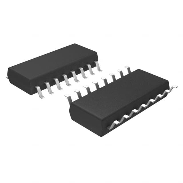
- Package: Small Outline Integrated Circuit (SOIC)
- Essence: Logic gate multiplexer
- Packaging/Quantity: Available in reels of 250 units
Specifications
The 74F257ASJX is a digital multiplexer integrated circuit designed for high-speed data selection. It operates on a supply voltage range of 4.5V to 5.5V and offers low power consumption, making it suitable for various applications.
Detailed Pin Configuration
The 74F257ASJX features a 16-pin Small Outline Integrated Circuit (SOIC) package. The pin configuration is as follows:
- A0 - Input A0
- A1 - Input A1
- A2 - Input A2
- A3 - Input A3
- B - Input B
- G - Enable Input
- Y0 - Output Y0
- Y1 - Output Y1
- Y2 - Output Y2
- Y3 - Output Y3
- VCC - Positive Supply Voltage
- Y4 - Output Y4
- Y5 - Output Y5
- Y6 - Output Y6
- Y7 - Output Y7
- GND - Ground
Functional Features
The 74F257ASJX is a quad 2-input multiplexer with output enable. It allows the selection of one of four data inputs (A0-A3) to be routed to the outputs (Y0-Y7) based on the control input (B). The enable input (G) controls the output state, enabling or disabling the outputs.
Advantages and Disadvantages
Advantages: - High-speed operation - Low power consumption - Compact SOIC package - Versatile multiplexing capabilities
Disadvantages: - Limited number of inputs (four) - Requires external control signals for proper operation
Working Principles
The 74F257ASJX operates based on the principles of digital logic. It utilizes a combination of gates and flip-flops to perform the multiplexing function. The control input (B) determines which data input (A0-A3) is selected and routed to the corresponding output (Y0-Y7). The enable input (G) controls the output state, allowing the outputs to be enabled or disabled.
Detailed Application Field Plans
The 74F257ASJX finds applications in various fields where digital data selection is required. Some potential application areas include:
- Data communication systems
- Digital signal processing
- Microcontroller-based systems
- Industrial automation
- Consumer electronics
Detailed and Complete Alternative Models
- 74HC257: Similar functionality with CMOS technology
- 74LS257: Lower power version with TTL technology
- CD4051: Analog multiplexer/demultiplexer IC
These alternative models offer similar functionality to the 74F257ASJX and can be used as substitutes depending on specific requirements.
Word count: 314 words
Liệt kê 10 câu hỏi và câu trả lời thường gặp liên quan đến ứng dụng 74F257ASJX trong giải pháp kỹ thuật
Sure! Here are 10 common questions and answers related to the application of 74F257ASJX in technical solutions:
Q: What is the 74F257ASJX? A: The 74F257ASJX is a quad 2-input multiplexer with tri-state outputs, commonly used in digital logic circuits.
Q: What is the purpose of a multiplexer? A: A multiplexer is used to select one of several input signals and route it to a single output line based on control inputs.
Q: How many inputs does the 74F257ASJX have? A: The 74F257ASJX has four data inputs (A, B, C, D) and two select inputs (S0, S1).
Q: How many output lines does the 74F257ASJX have? A: The 74F257ASJX has one output line (Y) for each data input, resulting in four output lines.
Q: What are the tri-state outputs? A: Tri-state outputs can be in one of three states: high (logic 1), low (logic 0), or high impedance (disconnected).
Q: How do I select an input using the 74F257ASJX? A: The select inputs (S0, S1) determine which input is routed to the output. Refer to the truth table in the datasheet for specific combinations.
Q: Can I connect multiple 74F257ASJX devices together? A: Yes, you can connect multiple 74F257ASJX devices together to create larger multiplexers or more complex logic circuits.
Q: What is the power supply voltage range for the 74F257ASJX? A: The 74F257ASJX operates with a power supply voltage range of 4.5V to 5.5V.
Q: What is the maximum operating frequency of the 74F257ASJX? A: The maximum operating frequency of the 74F257ASJX depends on various factors, including the specific application and circuit design.
Q: Are there any precautions I should take when using the 74F257ASJX? A: It is important to ensure proper decoupling capacitors are used near the power supply pins and to follow the recommended operating conditions mentioned in the datasheet to ensure reliable operation.
Please note that these answers provide general information about the 74F257ASJX, and it's always recommended to refer to the datasheet and consult technical documentation for specific details and application requirements.