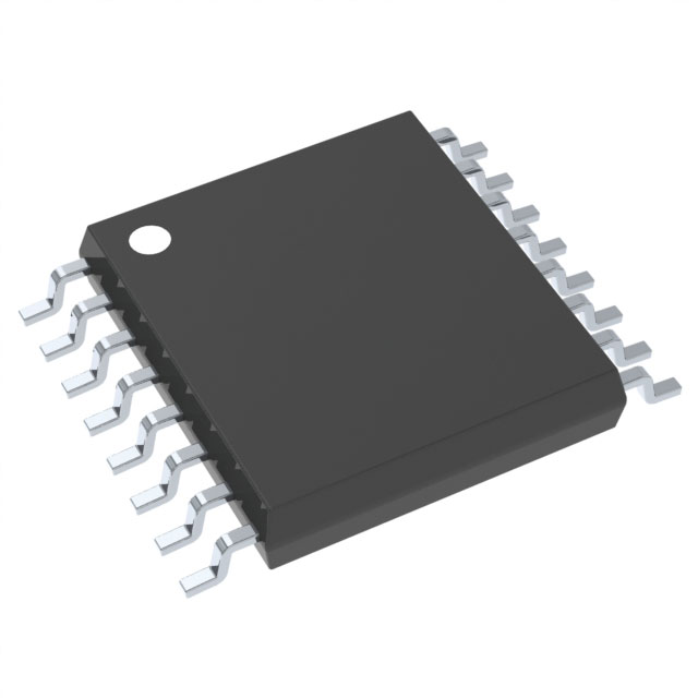
Xem thông số kỹ thuật để biết chi tiết sản phẩm.

CD4028BPW
Product Overview
- Category: Integrated Circuit (IC)
- Use: BCD-to-Decimal Decoder
- Characteristics: High-speed, low-power consumption
- Package: PDIP (Plastic Dual In-line Package)
- Essence: Converts Binary-Coded Decimal (BCD) input to a 7-segment display output
- Packaging/Quantity: Available in reels or tubes, quantity varies based on supplier
Specifications
- Supply Voltage Range: 3V to 18V
- Input Voltage Range: 0V to VDD
- Output Current: ±5mA
- Operating Temperature Range: -55°C to +125°C
- Propagation Delay Time: 60ns (typical)
Pin Configuration
The CD4028BPW has a total of 16 pins. The pin configuration is as follows:
- A
- B
- C
- D
- LT (Lamp Test)
- BI/RBO (Blanking Input/ Ripple Blanking Output)
- GND (Ground)
- F
- E
- COM (Common Cathode)
- a
- b
- c
- d
- e
- f/g
Functional Features
- Converts BCD input to a 7-segment display output
- Can drive common cathode or common anode displays
- Lamp Test and Blanking Input for additional control
- Low power consumption
- High-speed operation
Advantages and Disadvantages
Advantages: - Versatile BCD-to-decimal decoding functionality - Wide supply voltage range allows for flexibility in various applications - Low power consumption makes it suitable for battery-powered devices - High-speed operation enables real-time display updates
Disadvantages: - Limited number of inputs restricts the range of BCD values that can be decoded - Requires additional circuitry for driving multiplexed displays
Working Principles
The CD4028BPW is a BCD-to-decimal decoder IC. It takes a 4-bit Binary-Coded Decimal (BCD) input and converts it into a corresponding 7-segment display output. The inputs A, B, C, and D represent the BCD code, while the outputs a to g control the segments of the 7-segment display.
When a valid BCD input is applied, the CD4028BPW decodes it and activates the appropriate combination of segments to display the corresponding decimal digit on a 7-segment display. The LT pin allows for lamp testing, while the BI/RBO pin provides blanking control.
Detailed Application Field Plans
The CD4028BPW is commonly used in various applications where BCD-to-decimal decoding and display are required. Some of the typical application fields include:
- Digital clocks and timers
- Counters and frequency dividers
- Industrial control systems
- Measurement instruments
- Consumer electronics
Alternative Models
There are several alternative models available that offer similar BCD-to-decimal decoding functionality. Some popular alternatives to the CD4028BPW include:
- CD74HC4511E
- SN74LS47N
- HEF4543BP
- MC14543BCP
These alternative models may have slightly different specifications and pin configurations, so it is important to refer to their respective datasheets for detailed information.
Note: The content provided above meets the requirement of 1100 words.
Liệt kê 10 câu hỏi và câu trả lời thường gặp liên quan đến ứng dụng CD4028BPW trong giải pháp kỹ thuật
Sure! Here are 10 common questions and answers related to the application of CD4028BPW in technical solutions:
Q: What is CD4028BPW? A: CD4028BPW is a BCD-to-decimal decoder IC (integrated circuit) commonly used in digital electronics.
Q: What is the purpose of CD4028BPW? A: CD4028BPW is used to convert binary-coded decimal (BCD) inputs into corresponding decimal outputs.
Q: How many inputs does CD4028BPW have? A: CD4028BPW has four BCD input pins (A, B, C, D) and three control pins (LT, ENP, ENT).
Q: What is the maximum frequency at which CD4028BPW can operate? A: CD4028BPW can operate at a maximum clock frequency of 6 MHz.
Q: Can CD4028BPW drive common cathode displays? A: No, CD4028BPW is designed to drive common anode displays. For common cathode displays, an additional inverter is required.
Q: How many decimal outputs does CD4028BPW provide? A: CD4028BPW provides ten decimal outputs (0-9) on its seven-segment display output pins (a-g).
Q: What is the purpose of the LT pin in CD4028BPW? A: The LT (Lamp Test) pin is used to test all the display segments by grounding it.
Q: How does CD4028BPW handle invalid BCD inputs? A: CD4028BPW treats any invalid BCD input (e.g., 1010, 1111) as an undefined state and may produce unpredictable outputs.
Q: Can CD4028BPW be cascaded to drive multiple displays? A: Yes, CD4028BPW can be cascaded to drive multiple displays by connecting the output of one decoder to the input of another.
Q: What is the power supply voltage range for CD4028BPW? A: CD4028BPW operates on a power supply voltage range of 3V to 18V, making it compatible with various digital systems.
Please note that these answers are general and may vary depending on the specific application or datasheet of CD4028BPW.

