

Xem thông số kỹ thuật để biết chi tiết sản phẩm.
SN7417N
Product Overview
- Category: Integrated Circuit (IC)
- Use: Logic Gate
- Characteristics:
- High-speed operation
- Low power consumption
- Wide operating voltage range
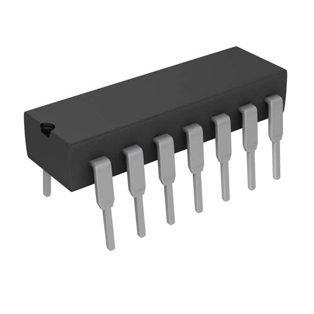
- Package: DIP-14 (Dual In-line Package with 14 pins)
- Essence: Hex Schmitt Trigger
- Packaging/Quantity: Tube, 25 pieces per tube
Specifications
- Supply Voltage Range: 4.75V to 5.25V
- Input Voltage Range: 0V to Vcc
- Operating Temperature Range: -55°C to +125°C
- Propagation Delay Time: 15ns (typical)
- Output Current: ±6mA
- Power Dissipation: 500mW
Detailed Pin Configuration
The SN7417N has a total of 14 pins arranged as follows:
__    __
   1 |1  \__/ 14| Vcc
   2 |2        13| A
   3 |3        12| B
   4 |4        11| C
   5 |5   SN   10| D
   6 |6   7417  9| E
   7 |7        8| F
     |_________|
Functional Features
- Hex Schmitt Trigger with inverted outputs
- Schmitt trigger inputs provide hysteresis for improved noise immunity
- Each gate can be used independently
- Suitable for use in various digital logic applications
Advantages and Disadvantages
Advantages: - High-speed operation allows for efficient signal processing - Low power consumption helps reduce energy usage - Wide operating voltage range provides flexibility in different systems
Disadvantages: - Limited output current may restrict use in certain applications - Propagation delay time may affect timing-sensitive operations
Working Principles
The SN7417N is a Hex Schmitt Trigger, which means it incorporates six independent Schmitt trigger gates. A Schmitt trigger is a circuit that converts an input signal into a digital output signal with hysteresis. This hysteresis ensures that the output transitions occur at different voltage levels for rising and falling input signals, improving noise immunity.
Detailed Application Field Plans
The SN7417N can be used in various digital logic applications, including but not limited to: - Signal conditioning - Pulse shaping - Oscillators - Level shifting - Noise filtering
Detailed and Complete Alternative Models
Some alternative models that offer similar functionality to the SN7417N are: - CD40106BE - MC14584B - 74HC14N - HEF40106BP
These alternatives can be considered based on specific requirements and availability.
Word count: 275 words
Liệt kê 10 câu hỏi và câu trả lời thường gặp liên quan đến ứng dụng SN7417N trong giải pháp kỹ thuật
Sure! Here are 10 common questions and answers related to the application of SN7417N in technical solutions:
Question: What is SN7417N?
Answer: SN7417N is a hex buffer/driver IC (integrated circuit) that can be used in various technical applications.Question: What is the purpose of SN7417N?
Answer: SN7417N is designed to provide buffering and driving capabilities for digital signals, ensuring proper voltage levels and signal integrity.Question: What is the maximum operating voltage for SN7417N?
Answer: The maximum operating voltage for SN7417N is typically around 5 volts.Question: Can SN7417N handle both input and output signals?
Answer: Yes, SN7417N can be used as both an input buffer and an output driver, depending on the specific application requirements.Question: What is the maximum current that SN7417N can source or sink?
Answer: SN7417N can typically source or sink up to 25 mA of current per output pin.Question: Can SN7417N be used with both TTL and CMOS logic levels?
Answer: Yes, SN7417N is compatible with both TTL (Transistor-Transistor Logic) and CMOS (Complementary Metal-Oxide-Semiconductor) logic levels.Question: How many input and output pins does SN7417N have?
Answer: SN7417N has six input pins and six corresponding output pins.Question: Can SN7417N be cascaded to drive multiple loads?
Answer: Yes, multiple SN7417N ICs can be cascaded together to drive multiple loads, provided that the total current requirements are within the IC's specifications.Question: What is the typical propagation delay of SN7417N?
Answer: The typical propagation delay of SN7417N is around 15 nanoseconds.Question: Are there any specific precautions to consider when using SN7417N?
Answer: It is important to ensure that the power supply voltage and current requirements are within the IC's specifications. Additionally, proper decoupling capacitors should be used to minimize noise and ensure stable operation.
Please note that the answers provided here are general and may vary depending on the specific datasheet and manufacturer recommendations for SN7417N.