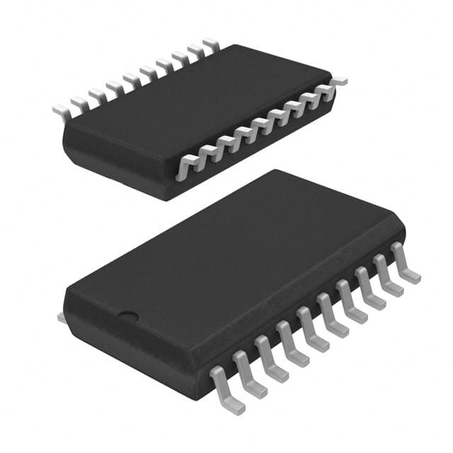
Xem thông số kỹ thuật để biết chi tiết sản phẩm.

SN74AS241ADWR
Product Overview
- Category: Integrated Circuit
- Use: Buffer/Line Driver
- Characteristics: High-speed, low-power, 3-state output
- Package: SOIC (Small Outline Integrated Circuit)
- Essence: Logic gate with 8-bit buffer and 3-state outputs
- Packaging/Quantity: Tape and Reel, 2500 units per reel
Specifications
- Supply Voltage Range: 4.5V to 5.5V
- Input Voltage Range: 0V to VCC
- Output Voltage Range: 0V to VCC
- Operating Temperature Range: -40°C to +85°C
- Propagation Delay Time: 6ns (typical)
- Output Current: ±24mA
- Input Capacitance: 3pF
- Output Capacitance: 15pF
Detailed Pin Configuration
The SN74AS241ADWR has a total of 20 pins, which are arranged as follows:
- GND (Ground)
- A1 (Input A1)
- B1 (Input B1)
- Y1 (Output Y1)
- A2 (Input A2)
- B2 (Input B2)
- Y2 (Output Y2)
- A3 (Input A3)
- B3 (Input B3)
- Y3 (Output Y3)
- A4 (Input A4)
- B4 (Input B4)
- Y4 (Output Y4)
- A5 (Input A5)
- B5 (Input B5)
- Y5 (Output Y5)
- A6 (Input A6)
- B6 (Input B6)
- Y6 (Output Y6)
- VCC (Power Supply)
Functional Features
- 8-bit buffer with 3-state outputs
- High-speed operation
- Low-power consumption
- TTL-compatible inputs and outputs
- Output enable control for 3-state operation
Advantages and Disadvantages
Advantages: - High-speed performance allows for efficient data transfer - Low-power consumption reduces energy usage - 3-state outputs provide flexibility in connecting multiple devices
Disadvantages: - Limited voltage range (4.5V to 5.5V) - Relatively small input and output capacitance limits its use in high-capacitance applications
Working Principles
The SN74AS241ADWR is a buffer/line driver integrated circuit that amplifies and buffers digital signals. It operates by receiving input signals on the A1-A6 and B1-B6 pins, and providing amplified output signals on the Y1-Y6 pins. The 3-state outputs allow the device to be connected to multiple devices without causing conflicts.
Detailed Application Field Plans
The SN74AS241ADWR is commonly used in various applications, including:
- Data communication systems
- Microprocessor-based systems
- Memory address drivers
- Clock distribution networks
- Bus interface circuits
Detailed and Complete Alternative Models
- SN74LS241: Similar functionality but operates at a lower speed.
- SN74HC241: Compatible with CMOS logic levels and has a wider supply voltage range.
- SN74ACT241: Offers faster propagation delay time and higher output current capability.
These alternative models provide similar functionality to the SN74AS241ADWR but may have different specifications or characteristics.
Word count: 399 words
Liệt kê 10 câu hỏi và câu trả lời thường gặp liên quan đến ứng dụng SN74AS241ADWR trong giải pháp kỹ thuật
Sure! Here are 10 common questions and answers related to the application of SN74AS241ADWR:
Q: What is SN74AS241ADWR? A: SN74AS241ADWR is a specific type of integrated circuit (IC) known as a buffer/line driver. It is commonly used in technical solutions to amplify and control digital signals.
Q: What is the purpose of using SN74AS241ADWR? A: The purpose of using SN74AS241ADWR is to provide signal buffering and line driving capabilities, ensuring proper voltage levels and signal integrity between different components or subsystems in a circuit.
Q: What voltage levels does SN74AS241ADWR support? A: SN74AS241ADWR supports a wide range of voltage levels, typically from 2V to 6V, making it compatible with various digital logic families.
Q: How many input/output lines does SN74AS241ADWR have? A: SN74AS241ADWR has 8 input/output lines, allowing it to handle up to 8 separate signals simultaneously.
Q: Can SN74AS241ADWR be used for bidirectional communication? A: No, SN74AS241ADWR is a unidirectional buffer/line driver, meaning it can only drive signals in one direction. For bidirectional communication, a separate IC or circuitry is required.
Q: What is the maximum current that SN74AS241ADWR can source/sink? A: SN74AS241ADWR can source/sink up to 24mA of current per output pin, making it suitable for driving standard TTL or CMOS logic loads.
Q: Does SN74AS241ADWR have any built-in protection features? A: Yes, SN74AS241ADWR has built-in overvoltage protection and thermal shutdown features to protect the IC from excessive voltage or temperature.
Q: Can SN74AS241ADWR be cascaded to drive more than 8 signals? A: Yes, multiple SN74AS241ADWR ICs can be cascaded together to drive a larger number of signals. The output of one IC can be connected to the input of another.
Q: Is SN74AS241ADWR compatible with other logic families like CMOS or TTL? A: Yes, SN74AS241ADWR is compatible with various logic families, including CMOS and TTL, as long as the voltage levels are within the specified range.
Q: Are there any specific precautions to consider when using SN74AS241ADWR? A: It is important to ensure that the power supply voltage and signal voltage levels are within the specified range. Additionally, proper decoupling capacitors should be used to minimize noise and stabilize the power supply.

