

Xem thông số kỹ thuật để biết chi tiết sản phẩm.
SN74HCT139DBR
Product Overview
- Category: Integrated Circuit (IC)
- Use: Decoder/Demultiplexer
- Characteristics: High-speed, CMOS technology
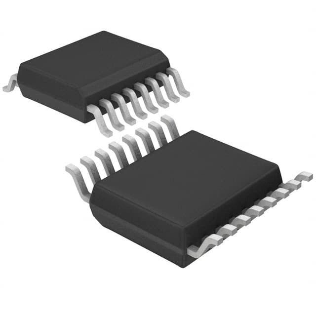
- Package: SSOP-16
- Essence: Dual 2-to-4 line decoder/demultiplexer
- Packaging/Quantity: Tape and Reel, 2500 pieces per reel
Specifications
- Supply Voltage Range: 2V to 6V
- Input Voltage Range: 0V to VCC
- Output Voltage Range: 0V to VCC
- Maximum Operating Frequency: 25 MHz
- Propagation Delay Time: 15 ns
- Low Power Consumption: 4µA (typical)
Detailed Pin Configuration
The SN74HCT139DBR has a total of 16 pins. The pin configuration is as follows:
- A0 - Input A0
- A1 - Input A1
- GND - Ground
- A2 - Input A2
- E1 - Enable Input 1
- Y0 - Output Y0
- Y1 - Output Y1
- Y2 - Output Y2
- Y3 - Output Y3
- E2 - Enable Input 2
- VCC - Positive Supply Voltage
- B0 - Input B0
- B1 - Input B1
- GND - Ground
- B2 - Input B2
- VCC - Positive Supply Voltage
Functional Features
The SN74HCT139DBR is a dual 2-to-4 line decoder/demultiplexer IC. It is designed to convert binary information from two input lines (A0-A2 and B0-B2) into four output lines (Y0-Y3). The enable inputs (E1 and E2) control the operation of the decoder/demultiplexer. When both enable inputs are high, the outputs are in a high-impedance state.
Advantages and Disadvantages
Advantages: - High-speed operation - Low power consumption - Wide supply voltage range - Compact SSOP-16 package
Disadvantages: - Limited number of input and output lines - Not suitable for complex decoding applications
Working Principles
The SN74HCT139DBR operates based on CMOS technology. The inputs A0-A2 and B0-B2 represent the binary information to be decoded. The enable inputs E1 and E2 control the operation of the decoder/demultiplexer. When the enable inputs are active, the selected output line(s) will reflect the binary input combination.
Detailed Application Field Plans
The SN74HCT139DBR can be used in various applications, including but not limited to: - Address decoding in microcontrollers and microprocessors - Data routing in multiplexing systems - Memory address decoding - Signal demultiplexing
Detailed and Complete Alternative Models
Some alternative models that can be considered as alternatives to the SN74HCT139DBR are: - 74HC139: Similar functionality, different package options - CD74HC139: High-speed CMOS version - 74LS139: TTL version with similar functionality
These alternative models offer similar decoding capabilities and can be chosen based on specific requirements and availability.
Word count: 314 words
Liệt kê 10 câu hỏi và câu trả lời thường gặp liên quan đến ứng dụng SN74HCT139DBR trong giải pháp kỹ thuật
Sure! Here are 10 common questions and answers related to the application of SN74HCT139DBR:
Q: What is SN74HCT139DBR? A: SN74HCT139DBR is a dual 2-to-4 line decoder/demultiplexer integrated circuit (IC) that can be used in various technical solutions.
Q: What is the purpose of SN74HCT139DBR? A: SN74HCT139DBR is used to decode binary information from two input lines into four output lines, making it useful for addressing, data routing, and selection applications.
Q: What is the voltage range supported by SN74HCT139DBR? A: SN74HCT139DBR supports a voltage range of 2V to 6V.
Q: How many inputs does SN74HCT139DBR have? A: SN74HCT139DBR has two input lines, A and B.
Q: How many outputs does SN74HCT139DBR have? A: SN74HCT139DBR has four output lines, Y0, Y1, Y2, and Y3.
Q: Can SN74HCT139DBR be cascaded to increase the number of decoded outputs? A: Yes, multiple SN74HCT139DBR ICs can be cascaded together to increase the number of decoded outputs.
Q: What is the maximum frequency at which SN74HCT139DBR can operate? A: SN74HCT139DBR can operate at a maximum frequency of 25 MHz.
Q: Does SN74HCT139DBR have any built-in protection features? A: Yes, SN74HCT139DBR has built-in diode protection to prevent damage from electrostatic discharge (ESD).
Q: What is the power supply voltage required for SN74HCT139DBR? A: SN74HCT139DBR requires a power supply voltage of 4.5V to 5.5V.
Q: Can SN74HCT139DBR be used in both digital and analog applications? A: No, SN74HCT139DBR is specifically designed for digital applications and is not suitable for analog use.
Please note that these answers are general and may vary depending on specific application requirements.