

Xem thông số kỹ thuật để biết chi tiết sản phẩm.
SN74S280NSRG4
Product Overview
- Category: Integrated Circuit (IC)
- Use: Logic Device
- Characteristics: High-speed, 9-bit parity generator/checker
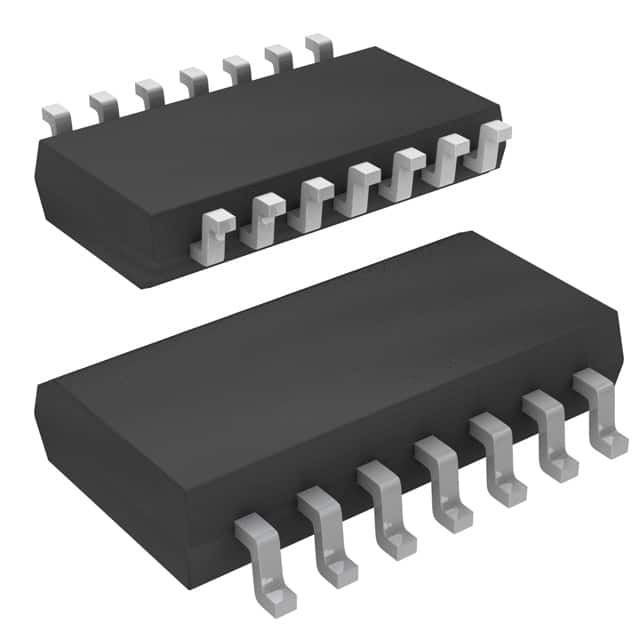
- Package: SOIC (Small Outline Integrated Circuit)
- Essence: Parity generator/checker IC
- Packaging/Quantity: Tape and Reel, 2500 units per reel
Specifications
- Supply Voltage Range: 4.5V to 5.5V
- Operating Temperature Range: -40°C to 85°C
- Input Current: ±10mA
- Output Current: ±20mA
- Propagation Delay Time: 7ns (typical)
- Power Dissipation: 500mW (max)
Detailed Pin Configuration
The SN74S280NSRG4 has a total of 14 pins. The pin configuration is as follows:
- GND (Ground)
- A0 (Input A0)
- A1 (Input A1)
- A2 (Input A2)
- A3 (Input A3)
- A4 (Input A4)
- A5 (Input A5)
- A6 (Input A6)
- A7 (Input A7)
- A8 (Input A8)
- P (Parity Output)
- C (Carry Output)
- G2 (Enable Input)
- VCC (Supply Voltage)
Functional Features
The SN74S280NSRG4 is a high-speed parity generator/checker IC. It can generate or check the parity of a 9-bit binary input. The device has an enable input (G2) that allows for easy control of the operation. The parity output (P) indicates whether the input has even or odd parity, while the carry output (C) signals if there is a carry generated during the addition of the input bits.
Advantages and Disadvantages
Advantages: - High-speed operation - Compact SOIC package - Easy control with enable input - Reliable parity generation/checking
Disadvantages: - Limited to 9-bit parity generation/checking - Requires external components for complete system integration
Working Principles
The SN74S280NSRG4 works based on the principles of binary addition and parity checking. It takes a 9-bit binary input and generates or checks its parity. The device uses internal logic gates and flip-flops to perform the necessary calculations. The enable input (G2) controls the operation, allowing the user to choose between generating or checking parity. The outputs (P and C) provide the results of the operation.
Detailed Application Field Plans
The SN74S280NSRG4 is commonly used in various applications that require parity generation or checking. Some of the detailed application field plans include:
- Data transmission systems: Ensuring data integrity by generating and checking parity during transmission.
- Error detection and correction: Parity checking can be used to detect and correct single-bit errors in data storage systems.
- Memory systems: Parity generation/checking in memory modules to ensure data accuracy.
- Network communication: Verifying data integrity in network protocols by performing parity checks.
- Industrial control systems: Implementing parity generation/checking for reliable data processing in control systems.
Detailed and Complete Alternative Models
- SN54LS280: Similar 9-bit parity generator/checker IC from Texas Instruments.
- MC74HC280: High-speed CMOS 9-bit parity generator/checker IC from ON Semiconductor.
- CD54HC280: High-speed CMOS 9-bit parity generator/checker IC from Texas Instruments.
These alternative models offer similar functionality and can be considered as alternatives to the SN74S280NSRG4.
Word count: 430 words
Liệt kê 10 câu hỏi và câu trả lời thường gặp liên quan đến ứng dụng SN74S280NSRG4 trong giải pháp kỹ thuật
Sure! Here are 10 common questions and answers related to the application of SN74S280NSRG4 in technical solutions:
Q: What is the SN74S280NSRG4? A: The SN74S280NSRG4 is a 9-bit parity generator/checker IC, commonly used in digital systems for error detection and correction.
Q: What is the operating voltage range of SN74S280NSRG4? A: The operating voltage range of SN74S280NSRG4 is typically between 4.5V and 5.5V.
Q: How many inputs does SN74S280NSRG4 have? A: SN74S280NSRG4 has 9 inputs (A0-A8) for data bits and an additional input (G) for generating/checking parity.
Q: What is the output format of SN74S280NSRG4? A: The output of SN74S280NSRG4 is a single output pin (P) that indicates the parity status of the input data.
Q: Can SN74S280NSRG4 be used for both parity generation and checking? A: Yes, SN74S280NSRG4 can be used for both generating and checking parity, depending on the input configuration.
Q: What is the maximum clock frequency supported by SN74S280NSRG4? A: SN74S280NSRG4 can operate at a maximum clock frequency of 33 MHz.
Q: Is SN74S280NSRG4 suitable for high-speed applications? A: Yes, SN74S280NSRG4 is designed to work well in high-speed digital systems.
Q: Does SN74S280NSRG4 have any built-in error correction capabilities? A: No, SN74S280NSRG4 is primarily used for error detection and does not have built-in error correction features.
Q: Can SN74S280NSRG4 be cascaded to handle larger data widths? A: Yes, multiple SN74S280NSRG4 ICs can be cascaded together to handle larger data widths by connecting the outputs of one IC to the inputs of another.
Q: What are some typical applications of SN74S280NSRG4? A: SN74S280NSRG4 is commonly used in communication systems, memory modules, data storage devices, and other digital systems where error detection is critical.
Please note that these answers are general and may vary depending on specific design requirements and datasheet specifications.